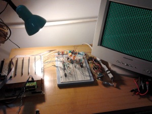
The VGA board prototype is finished now – including parallell to serial interface. The biggest problem – synchronization between Z80 writes and Atmega reading was resolved using 7474 flip-flop as planned before. Atmega328 source code in assembler is available upon request.
The final version of the video board is capable of displaying 40×33 characters using 8×12 pixel font. The interface of this board takes X and Y coordinates and 8 bit data (ascii). A single write of a character to the screen requires only one assembler instruction with three parameters:
ld b, 32 ;Y – max. 32
ld c, 39 ; X – max. 39
ld a,65 ;ASCII code is placed in A register here
out ( C ), A ;Display the character at given position.
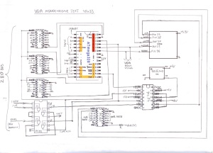
The VGA board converts the parallell data to serial signals, and places the data into video memory inside AVR chip. This process takes place during 2 horizontal blanking times (1st. blanking: readout of X and Y coordinates, 2nd blanking: shifting in the ASCII data). 74LS32 and 74HCT74 are producing /WAIT signal for the CPU, which prevents it from writing new data before actual is processed.
The results of initial tests showed that troughput of the video board interface is surprisingly high. It seems that there will be no need for special AVR code routines to speed some operations like filling the screen, clearing it , copying/moving data, etc. Everything can be done in Z80 code using simple I/O writes to video board registers. However, there is still a possibility to implement some sort of command list for the video controller: Suggessted way od implementing it is to use the video memory area just above the video buffer for writing commands and additional data. AVR could execute given commands and manage the command buffer during the vertical blanking period. However, there is a little problem with this solution: If , let`s say, a “clear screen” command would be issued at the start of a frame, and some time later there would be some writes to video memory, the result will be that those writes would be wiped out by the earlier issued command during the vertical blanking time. The easiest way to prevent this would be to insert a ~1/70 second delay after issuing the command, to ensure proper execution. It could also be useful t generate a /WAIT signal for the CPU , just like in a regular write operation (but for a longer period – to the end of the frame)
The prototype during operation:
A sketch of the circuit drawn just from the prototype board:


