Despite having recently very little time for playing around with the COSMAC ELF computer, I`ve managed to add some features and push the project just a little step forward.
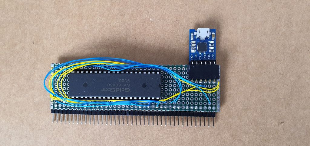
First, as a top priority, I had to put together the UART card, and write a rudimentary piece of code that will allow me to quickly download and run any software written on the PC. Thanks to the work that had already been done in form of the I/O frontend card, the UART module consists of just the 16C450 chip and a goldpin socket for USB to UART converter:

The GM16C450 IC is hardwired at I/0 address „2” and it`s register selection address lines A0-A2 are connected to respective signals on the system I/O section bus, so the register selection is achieved by writing appropriate 3 bits of data to register selection latch (I/O address „1”) on the I/O frontend card. Now I had to write the code for serial bootloader that will write data from UART to RAM and in the end it will perform a long branch to user program entry point in memory. From my previous experiences with Z80 and 6502 projects I learned that software development process for such small systems requires hundreds or thousands repetitions of the same processes like: assembly on PC, put the board to bootloader mode, prepare the terminal program, find the binary file, upload it and finally: run the code on the target board. So to make life easier I now always try to simplify the process as much as possible, all cheats and tweaks are always welcome here. For ELF computer, I came up with a simple bootloader idea that suits my needs. I`ll describe it`s work in points below:
- Initialize the 16450 chip and pool for incoming data.
- Start writing consecutive bytes to RAM at address 0003h
- Continue writing fixed amount of bytes (arbitrary chosen value of 2KB)
- Long branch to address 0003h
The source code for the bootloader is below:
; CDP1802 Computer - serial bootloader.
; Program sits at the begining of ROM, address 8000h
;
; Copies 4K from UART to RAM at destination address 0000h.
; If the file is smaller - just sits and waits - you have to manually reset the computer
;
; tasks:
; - Set necessary R registers to needed values
; - Initialize UART
; - loop outer = fixed block size, decrementing
; - loop inner = reading status information, reading and storing data byte to destination location

ADDRESS_LATCH	.equ	1h
UART_PORT		.equ	2h
DEST_ADDR		.equ	0000h
SIZE:			.equ	1000h + 100h; 4KB


				.org 8000h

				; Setting up R1 for UART init data;

				ldi LO,UART_init
				plo R1
				ldi HI,UART_init
				phi R1

				; Setting up R2 for data destination

				ldi LO,DEST_ADDR
				plo R2
				ldi HI,DEST_ADDR
				phi R2


				ldi LO,SIZE
				plo R3
				ldi HI,SIZE
				phi R3

				; sending init data for UART: 9600bps, 8bit data, 1bit stop, no party and flow control
				; total of four bytes must be send to different UART registers

				sex R1					;set register X=1 -> R1 will be data pointer

				out ADDRESS_LATCH
				out UART_PORT
				out ADDRESS_LATCH
				out UART_PORT
				out ADDRESS_LATCH
				out UART_PORT
				out ADDRESS_LATCH
				out UART_PORT

				seq						;LED indicates that UART is ready and waiting for data.

outer_wait:								;loading loop counter
				seq
				out ADDRESS_LATCH		;set latch for Line Status Register
wait:			inp UART_PORT			;D now has value of status register


				ani 1h					;masking out bit 0 of status register
				shr						;-> 0= no data yet, 1= data ready for readout
				bnf wait				; we are waiting for byte from UART

				out ADDRESS_LATCH		;reading from data holding register
				inp UART_PORT

				req

				str R2					;storing byte at destination address
				inc R2					;increment destination pointer

				dec R1					;decrement R1 so it will be
				dec R1					;pointing to holding register address

				dec R3					;decrementing loop counter
				ghi R3					;checking only high byte
				bnz outer_wait			;if it is 0 then we are done, if not - wait for another byte

				req						;all bytes received - LED off

				idl						;stop and do nothing;


UART_init:		.db 03h,83h,00h,0ch,01h,00h,03h,03h
				.db 05h,00h,00h				;05h - LSR address, 2x dummy bytes
											;(in ROM, so writing will not affect them, can be used as
											;temporary placeholders

;--------------------------------------------------------------------------------------------------------
; Second variant of bootloader - code starting from 0003h, size 2KB automatic long branch to program entry point
; after loading fixed size data block from UART. This bootloader is origins at 8100h
;--------------------------------------------------------------------------------------------------------

DEST_ADDR2		.equ	0003h
SIZE2:			.equ	0800h + 100h; 2KB


				.org 8100h

				; Setting up R1 for UART init data;

				ldi LO,UART_init2
				plo R1
				ldi HI,UART_init2
				phi R1

				; Setting up R2 for data destination

				ldi LO,DEST_ADDR2
				plo R2
				ldi HI,DEST_ADDR2
				phi R2


				ldi LO,SIZE2
				plo R3
				ldi HI,SIZE2
				phi R3

				sex R1					;set register X=1 -> R1 will be data pointer

				; sending init data for UART: 9600bps, 8bit data, 1bit stop, no party and flow control
				; total of four bytes must be send to different UART registers

				out ADDRESS_LATCH
				out UART_PORT
				out ADDRESS_LATCH
				out UART_PORT
				out ADDRESS_LATCH
				out UART_PORT
				out ADDRESS_LATCH
				out UART_PORT

				seq						;LED indicates that UART is ready and waiting for data.

outer_wait2:								;loading loop counter
				out ADDRESS_LATCH		;set latch for Line Status Register
wait2:			inp UART_PORT			;D now has value of status register


				ani 1h					;masking out bit 0 of status register
				shr						;-> 0= no data yet, 1= data ready for readout
				bnf wait2				; we are waiting for byte from UART

				out ADDRESS_LATCH		;reading from data holding register
				inp UART_PORT

				str R2					;storing byte at destination address
				inc R2					;increment destination pointer

				dec R1					;decrement R1 so it will be
				dec R1					;pointing to holding register address

				dec R3					;decrementing loop counter
				ghi R3					;checking only high byte
				bnz outer_wait2			;if it is 0 then we are done, if not - wait for another byte

				req						;all bytes received - LED off

				lbr 0003h				;jump to user program


UART_init2:		.db 03h,83h,00h,0ch,01h,00h,03h,03h
				.db 05h,00h,00h				;05h - LSR address, 2x dummy bytes
											;(in ROM, so writing will not affect them, can be used as
											;temporary placeholders
				.org 81ffh
				.db 0						;staring point for IDIOT/4 monitor in ROM

				.end
My workflow is like this: Power on the ELF, put it in LOAD mode and enter long branch instruction to bootloader entry point. For 8000h the bytes will be:
C0 80 00
Now put the ELF in RUN mode. It will start executing the bootloader code. Q LED turned on will indicate that 16C450 is ready to accept incoming bytes over the serial interface. Now from the terminal program on the PC send the object file in binary format . ELF will write the bytes to RAM and immediately after this it will jump to starting address 0003h and begin executing the user code. If you want to repeat the proces you just have to briefly reset the ELF, as it already has the appropriate long branch instruction at address 0000h and will therefore execute the bootloader routine again. This greatly speeds up the software development process. User program needs to fulfill just two minor requirements: it must originate at 0003h , and has to be exactly 2K long, so padding needs to be done during assembly. Here is an example code for blinking Q LED:
;Demo program 3
;Clasic Q LED blinking program

			.org 03h
start:
			req
delay:		        ldi 16
			phi 1
dlyloop:	        dec 1
			ghi 1
			bnz dlyloop
			bq start
			seq
			br delay
			.org 800h + 3h ;Add padding to fixed size of 2KB
			.db 0 			;dummy byte
			.end
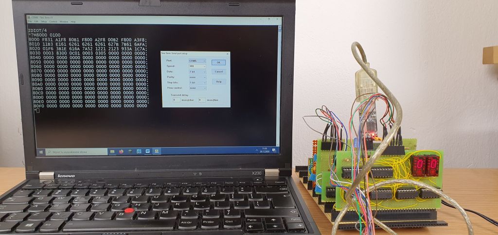
I also decided to make another variant of bootloader that will upload the code to starting address 0000h which is more suitable for running third party software. After both bootloaders started to work, I thought it would be fun to try running some more serious software on the machine, like basic interpreter or IDIOT/4 monitor from Mike Railey. It turned out that I only have to add a bit banged serial interface to the computer and upload the code – that`s it! As a first try I went for the IDIOT/4 monitor. For increased compatibility I decided to use inverted Q and /EF3 pins from the CPU. After making the necessary changes in EQU declarations in the source, I assembled it with A18 assembler, and uploaded it to RAM. Then I had to figure out working settings for the terminal and serial port on the PC. After some trial and error I finally got the IDIOT/4 working ! Here is the photo of the IDIOT/4 monitor in action, and also the settings in TeraTerm that worked for me:

I could only use the speed of 300bps, most probably that I use 1.8Mhz clock and not 2Mhz which i more suitable for classic ELF.
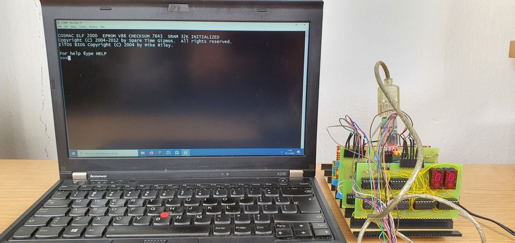
Encouraged by this success, I also tried uploading and running Tiny BASIC interpreter, however it had some issues that I didn`t bother to dig into, because a much better alternative appeared on the horizon – firmware for the Spare Time Gizmos ELF 2K ! After quick research I realized that there will be no problem for porting it on my ELF – in default the firmware uses inverted Q and /EF3 lines, and resides at 8000h address in ROM. All I had to do was to upload the hex file, version 88 firmware to the FLASH memory, set the serial port speed to 2400Bps / 8bit data / 1bit stop and manually jump to 8000h. Everything went smoothly. POST procedure went OK as expected, and after autobaud process was done, I was greeted with ELF2K welcome message!

ELF 2K firmware is a very rich and well-crafted software pack. Of course I`m not able to use most of the hardware specific functions like video display or RTC, but there are still all the basic features available that I would ever need: BASIC and FORTH interpreter, assembler, good monitor with option for code uploading in HEX format and some test routines. I especially liked the Tiny BASIC interpreter which works perfectly and is super fun to use! Check the video below – I`m entering a sample program in BASIC that uses OUT instruction, so to show that you can also interact with the hardware right form the BASIC program !
I definitely wanted the ELF2K firmware to stay with my computer. However, the firmware occupies all the 32KB ROM address space, leaving no place for my own bootloaders which are still the fastest solution for quick development. To overcome this problem I added a small feature to the memory card: a jumper that allows me to switch between two banks of 32KB ROM memory by forcing A14 address line either to 0V or to 5V. Now I had to prepare a binary file consisting of ELF2K firmware and my own set of bootloaders + IDIOT/4 glued together. I uploaded this combined bin file into the flash chip, and that`s it. Now I can choose to use either ELF2K firmware or my own pack whenever I want by just switching the jumper – even when the computer is on (it would of course be most reasonable to it when computer is not in the RUN mode)
The final bin file is here:
https://drive.google.com/file/d/1zGM1PMFS4_7oVQTXkPSOfHhFEYCm3-KL/view?usp=sharing
It can be burned directly to ROM chip. Memory map is here:
Bank 0:
ELF2K firmware.
Bank 1:
8000h – bootloader, dest address 0000h. Fixed code size 4KB.
8100h – bootloader, dest. Address 0003h. Fixed code size 2KB, automatic branch to 0003h.
8200h – IDIOT/4 monitor (uses inverted Q and /EF3 lines for console).
I`m very happy with the progress I made in a limited time budget I recently have. I managed not only to write serial bootloader but successfully integrated some sophisticated third party software for my computer. I also prepared hand-written schematics for all the cards, that will be helpful when I`ll be designing PCBs in Eagle.
My current plan is to put some thinking into computer`s user interface (LEDS, switches) and slow / single step clock functionality, because during initial experiments it turned out that those matters are more complicated that I initially thought – it is not difficult to implement it in some straightforward way, but it is much tedious to do it so it would be really functional and useful for debugging and education. Besides that, I hope I could get more fluent in 1802 assembly, because I still can`t get a good feeling of it. This CPU`s architecture is so different from what I`m used to that writing just any simple program is still a painful and slow process for me…
