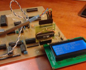
I`ve managed to build the bootloader system. I`ve used an Atmega8 @ 8Mhz internal clock. With Z80@4Mhz I`ve reached a maximum bandwidth of 38400 bps and a delay of 50us during assembly of two 4-bit parts to one byte of data. This speed is more than enough for the whole project. The bootloader add-on module has been built on a piece of universal PCB and included 2×10 pin headers for easy attachement to motherboard and serial cable. This module could be easily used for various other projects in the future. The speed could be adjusted in hardware (by jumpers) or using serial terminal.
Operation of the bootloader system goes like this:
– On the PC side I use TeraTerm – great piece of software, lots of options and easy to use. It has a binary RAW mode which works perfectly with my bootloader.
– Atmega8 receives bytes from UART, divides them in two 4-bit pieces, adds control signals and puts them out on it`s output ports pins. These signals go directly to 74LS245 on the Z80 system`s motherboard input port.
-On the Z80 side I`ve placed a small program in ROM memory: After reset, the CPU waits for the transmision to began on port FFFFh. After detecting a start condition, the program reads 4-bits pieces of data, combines them together and puts them in RAM memory starting from address 8000h. After receiving a stop condition, the CPU performs a jump to address 8000h thus executing the user program that was just downloaded.
Below you can see a the bootloader add-on board attached to motherboard`s input port pins. The 4-wire cable on top of the bard goes to a RS232-TTL converter and then – to PC`s serial port. The top goldpin header also includes ISP programmer interface for the Atmega8.

