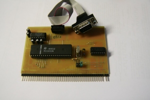
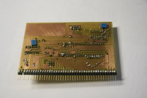
Today I`ve completed the UART board, here are the photos of the PCB:
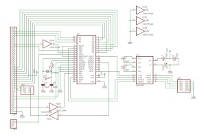
I was wondering about the interrupt functionality of 16450. I haven`t really planned to use it, and was going to disable it for good in the final version of the PCB.However, I`ve decided to leave a possibility to use the interrupts in the future by adding jumpers which allows me to select /INT /NMI or NONE.
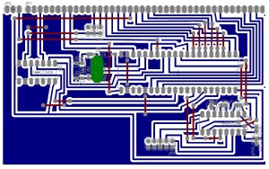
Schematics and PCB design are below:
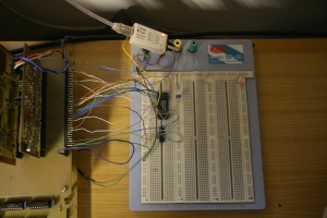
A Z80CTC chip was also tested today. I`m planning to use the CTC`s interrupt functionality extensvely in C-Z80, so this IC will be connected to /INT pin of the system bus. The connections were rather straightforward , and besides the CTC I`ve only used 74HCT32 for address decoding. The decoder produces a logical OR between A6,A7 and NAND(A8-A15). Lines A0 an A1 are connected to CS0 and CS1 of the CTC. This setup places the CTC in address range of ff00h to ff03h. The test circuit is shown below:
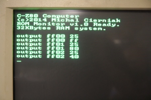
The logic probe seen on the upper part of the screen is connected to ZC/TO output pins of channed 0, 1 and 2. After programming the CTC with folowing commands:
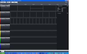
Which starts channells 0,1,2 in timer modes with prescalers of 256 and time constants of ffh, 80h and 40h I observed these waveforms on ZC/TO pins:
The period between pulses on channel 0 is about 16ms , on channel 1 – 8ms and on channel 2 – about 4ms. The chip seems to be working fine. Interrupts haven`t been checked yet, but there is no reason they shouldn`t be working also. The CTC will be working with Z80 in interrput mode 2. At this moment I`m not planning to use other interrupt capable devices besides earlier mentoined 16450 which could work on NMI if I would need serial port interrputs badly.

